A gripper module for collaborative manipulation and construction
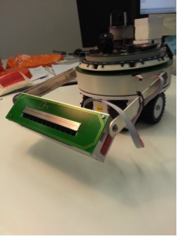 The group of marXbots robots used for validation of swarm algorithms in the ASCENS project has been equipped with a gripper module enabling collaborative manipulation and construction.
You can observe just above the robot equipped with the gripper and below the CAD version of the module.

The module is a magnetic gripper that allows taking ferromagnetic objects. It is based on a magnetic switch that can either attract the objects or not, depending on its configuration. To change the configuration, the magnet can be rotated inside a ferromagnetic structure that conducts the flux inside or outside of it, in respect of the magnet position.This generate an external attraction or not, allowing to grasp or not the objects. The switch between configurations is made by a motor.
In the following figure you can see the magnetic principle of the switch:

This gripper module has a total of tree degrees of freedom in addition of the magnetic switch. The first one is the rotation of the arm in respect to the body of the robot. This is important to precisely manipulate objects and structures, it is also primordial if you want that several robots grasp the same object and move it collaboratively. Sliding connectors allow rotating continuously.
The second degree of freedom is the lifting movement of the arm. This degree of freedom is powerful enough to lift more than 100g and bring objects to a position higher than the robot size.
The third degree of freedom is the tilt of the hand, for instance allowing to keep horizontal a cube used in the construction of walls.
The gripper module has several sensors:
- All degrees of freedom have position and torque feedback, allowing control in position, speed and torque.
- There are 22 IR proximity sensors on the gripper. 10 are located in front, 10 under and 2 on each side of the gripper.
- In the front of the gripper we have designed a RFID reader and writer, very interesting for the recognition of objects.
- On the arm there is a force sensor that measures the lateral bending of it.
Here a CAD overview of this mechatronic system:
![]()
The gripper that has been developed in ASCENS is a key element to progress the exploration of robotic technologies. Here an example of manipulation of objects:
Author Michael Bonani, Francesco Mondada
Distributed Exploration with a Robot Swarm
Engineering Robot Swarms
Large multi-robot systems (robot swarms) have the potential to display desirable properties, such as robustness to individual failures through redundancy, and enhanced performance through parallelism and cooperation. Realizing such potential is challenging because of the lack of sound design methodologies.
In the literature, coordination among multiple robots has been achieved in several ways. Existing approaches span from complete centralization to complete decentralization, with hybrid centralized-decentralized systems in between. With complete centralization, a master system must collect the data from the robots, analyze it and send the actions to perform to each robot. In many applications, the advantages of this approach do not counterbalance its drawbacks. Although centralized control is usually simpler to design and can result in a globally optimized behavior, it suffers from poor robustness (the master system is a single point of failure) and poor scalability (the master system's CPU and network connectivity are shared resources), and it requires global sensing and communication (which is not always available).
In contrast, completely distributed coordination algorithms do not exploit any kind of master system, global knowledge, or planning. Instead, coordination is the result of the parallel pairwise interactions of the system's components. Completely distributed coordination algorithms achieve scalability through local sensing and communication, and achieve robustness and high performance by leveraging the natural parallelism and redundancy of the system. However, it is very hard to design effective coordination algorithms of this kind.
A promising approach to the design of swarm robotics systems is a combination of behavior-based (compositional, pattern-based) aspects and automatic procedures (not restricted to optimization methods). The work in the ASCENS project followed the line of research that leads to the definition of such a combined approach.
Awareness and Adaptation in Robot Swarms
The notions of awareness and adaptation in robot swarms can manifest themselves at the individual level and at the ensemble level. For the purposes of ASCENS, our primary focus is modeling and achieving ensemble-level awareness and adaptation. However, the two levels are deeply intertwined---a study of ensemble awareness/adaptation cannot neglect the individual level. Individual awareness and adaptation can be defined as the ability of the robot to estimate its own state, as well as a relevant portion of the ensemble state, and react effectively to state changes. By relevant portion, here we mean that the robot must be capable of retrieving enough information about the ensemble state to make decisions leading to correct ensemble behaviors. Ensemble awareness and adaptation refer to the capability of the ensemble to behave as a coherent unit, by distributing information correctly and acting in a coordinated fashion.
The relationship between the individual and the ensemble levels is complex. For instance, a high degree of individual awareness is not required to produce complex ensemble behaviors which display high degrees of awareness. Research on social insects show that individuals following simple rules based on short-range information about the environment are capable of highly complex and efficient behaviors such as nest construction and food foraging. The algorithm described in the next section is an example of an individual behavior based on short-range information and little individual awareness that result in a complex ensemble behavior.
Scenario: Exploration of an Unknown Environment by a Robot Swarm
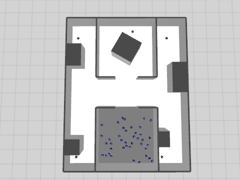
The application scenario can be summarized as disaster recovery. We imagine that a disaster happened, such as the catastrophic failure of a nuclear plant, or a major fire in a large building. We also imagine that an activity of search-and-rescue must be performed. For instance, people may be trapped inside the building and they must be found and brought to safety. Given the high danger of operating in such environment, it is realistic to think that an ensemble of robots could be used to perform the most dangerous activities. Among these activities, two are the focus of our attention: exploring the environment and finding targets to rescue.
The environment is a large rectangular area structured by several walls. The victims to find are scattered throughout the environment. For the purposes of the ASCENS project, there was no real need to design a specific object to be retrieved. Thus, we used a robot that we suppose unable to move. The explorer robots are initially deployed in the gray deployment area.
A Fully Distributed Solution
We present a fully distributed algorithm for collective exploration. The algorithm works under the assumption that the robots are initially unaware of the whereabouts of the victims and of the structure of the environment. The concepts of awareness and adaptation play a fundamental role in this application.
In terms of awareness, the most important requirement is that the ensemble as a whole is capable of representing the current knowledge regarding the structure of the environment. The ultimate purpose of exploration is to allow a second set of robots, the rescuers, to reach the victims that need assistance.
To achieve this result, one could endow each robot with an algorithm for simultaneous localization and mapping (SLAM) and let the robots integrate each others' maps through communication. With this approach, the representation of the whole environment is a composition of the individual representations of each robot. While this approach is effective, it requires adequate sensing and computation capabilities on the robots. Moreover, this approach does not target the intrinsically distributed nature of the systems we studied throughout the project---in principle, a robot could solve the exploration task alone, given sufficient time and resources.
In this section we focus on an alternative solution, in which the robots construct a coherent collective representation of the environment without requiring SLAM capabilities. In terms of awareness, this algorithm demonstrates how little (or even zero) individual awareness can result in effective and coherent ensemble awareness.
The core idea behind the algorithm is to employ the robots as landmarks. A landmark robot occupies a specific location of the environment and maintains communication with a number of immediate neighboring landmarks. Upon receipt of a request for direction to a specific victim by a wandering robot, two situations can occur:
- The landmark can see the victim directly: in this case, the landmark sends the direction to the victim;
- The landmark cannot see the victim: in this case, the landmark propagates the request to its neighbors, and then picks the shortest suggested path
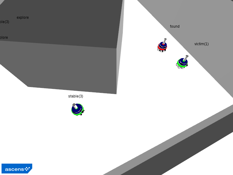
A diagrammatic representation of the algorithm is reported in the following figure, while the main phases of a typical execution of this behavior are illustrated in the subsequent snapshots of a simulation executed with the ARGoS simulator. The code itself is available here.
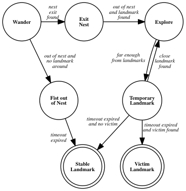
Phase 1: The first explorer exits the nest and becomes a stable landmark.
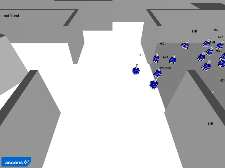
Phase 2: The other robots exit the nest.
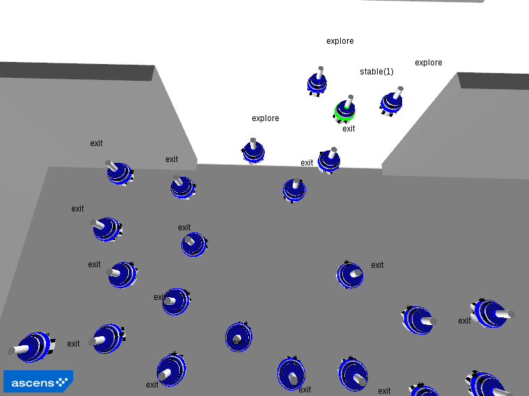
Phase 3: The explorers navigate the environment, occasionally becoming stable landmarks.
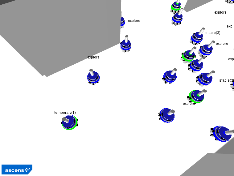
Phase 4: Explorers that are close to a victim become victim landmarks.
Global Parking Allocation
The e-Mobility case study aims at solving global problems, involving large ensembles of different vehicles. Such large problems tend to be complex to solve and often a globally optimal solution may be impossible to find. For this reason specific strategies are needed to solve them. In particular, we are interested in the parking optimization problem, consisting in finding the best parking lot for each vehicle of an ensemble. The best parking lot is chosen by considering: the distance from the current location of the vehicle to the parking lot, the distance from the parking lot to the appointment location and the cost of the parking lot.
We present two approaches to solving the parking optimization problem, joint work between Ugo Montanari, Giacoma Valentina Monreale and Matteo Sammartino at the University of Pisa, and Nicklas Hoch, at Volkswagen AG, Corporate Research Group in Wolfsburg. These approaches are based on the coordination of declarative and procedural knowledge. Declarative knowledge consists in a global description of the problem and its structure, in terms of its subproblems. General algorithms can be applied at this level, with high computational cost. Procedural knowledge defines which strategies should be applied to subproblems, and how their solutions can be combined into a possibly suboptimal, but acceptable global solution. Strategies are often more efficient than general algorithms, because they rely on specific knowledge about problems, which could also allow for the application of heuristics in order to improve the computational cost.
Both approaches are based on the representation of optimization problems as Soft Constraint Satisfaction Problems (SCSPs) [1], that are Constraint Satisfaction Problems where constraints are soft, meaning that they are preferred, but not required to be satisfied. Preference is formalized as a cost associated to each assignment of constraint variables. Optimality is defined in terms of the overall cost, which should be typically minimized.
Soft Constraint Logic Programming
The first approach consists in decomposing the global optimization problem in many local optimization problems, one for each vehicle of the ensemble, consisting in determining the best parking lot for it. All these local problems are solved separately by using an implementation of Soft Contraint Logic Programming (SCLP) [2]. The orchestrator implementing the coordination strategy then receives the results of all the local optimization solutions and checks if the local solutions all together form an admissible global solution, i.e., if no parking lot receives a number of cars larger than its capacity. If it is so, the problem is solved, otherwise the orchestrator queries the declarative knowledge again, but now by increasing the costs of the parking lots which received too many requests. The procedure is repeated, with suitable variations, until a global solution is found. Notice that in this way the orchestrator has a hypothetical, transactional behavior, with the options of committing (a solution is found) or partially backtracking (on the parkings which are overfull). The solution is guaranteed to be just an acceptable global solution: it may or may not be globally optimal. However, sub-optimality is in general needed to solve the problem in reasonable time.
The choice of SCLP is justified by its flexibility and expressiveness. On the one hand, the programmer could easily use SCLP to experiment on various optimization strategies for this and other more complex problems for electric vehicles. On the other hand, the interaction between the local optimizer and the global orchestrator is easier if the latter is declarative as it is the case for SCLP.
The coordination technique has been implemented in a demo application. We used Java for the orchestrator and CIAO [3] to model and solve the local problems. The figure below shows one phase of this execution.

There, four vehicles, represented by the markers A, B, C and D are finding a parking lot. Parking lots are represented by circles and each has a capacity of two vehicles. Each vehicle has autonomously computed the best parking lot for it and has sent its local solution to the Java orchestrator. Therefore, the vehicles A, B and D would like to park in the rightmost parking lot, while C prefers the parking lot at the lower part of the map. The orchestrator checks if each parking lot is able to satisfy the requests of the vehicles. In this case, since there are too many requests for the rightmost parking lot, the orchestrator increases the cost of it and asks the vehicles to recompute new local solutions.
Details about SCLP approaches to e-mobility optimization problems in ASCENS can be found in [5,6].
An algebraic approach to SCSPs
The second approach consists in representing SCSPs as terms of an algebraic specification, similar to a process calculus. These terms are then inductively evaluated in a domain of cost functions, where operators are interpreted as optimization steps. Using a dynamic programming approach, optimization is then carried out on these functions. The crucial point is that syntax also determines the variable elimination strategy, i.e., a solution to the secondary optimization problem of dynamic programming.
In order to illustrate this approach in more detail, we consider the term
(x1)(x2)(x3) ( A(x1,x3) ‖ B(x2,x3) ‖ C(x2) )
It represents a system with three parking zones A,B and C. Variables represent vehicles, and atomic terms A(x1,x3), B(x2,x3), C(x3) tell which vehicle can be parked in each zone. Each restricted variable must be parked in one of the zones within its scope.
Each zone comes with two pieces of information: a capacity and a function telling the cost of parking vehicles inside the zone. This allows us to give cost functions for each atomic subterm, and to inductively construct functions for complex terms. Restrictions is interpreted as variable elimination: the cost function in its scope should be optimized w.r.t. the restricted variable. Therefore, the position of restrictions determines a solution for the secondary optimization problem.
In the term shown above, restrictions are all outside (we say that the term is in normal form), meaning that we optimize w.r.t. all variables at once. This is inefficient, because it is clear that x1 must be parked inside A and x2 inside either B or C. Therefore, we introduce a scope extension axiom that allows restrictions to be moved. The following term
(x3)( (x1)A(x1,x3) ‖ (x2)( B(x2,x3) ‖ C(x2) ) )
is said to be in canonical form (namely no restriction can be pushed inside further) and describes a more efficient solution for the secondary optimization problem.
Given a SCSP term p, an essential property is that its cost function can be represented as a finite table, because only assignments to free variables of p matter. This allows computing cost functions using dynamic programming with tabling. More precisely, one can proceed in a bottom-up style, from atomic subterms to increasingly complex terms; tabular representations of cost functions are computed the first time they are encountered, once and for all.
An example is shown in the following figure, where double square brackets denote the evaluation operation that gives cost functions for terms. Tables (a)-(c) show cost functions for each zone. Actual cost entries are arbitrary. The leftmost columns indicates whether a car is parked inside (✓) or outside (-) the subsystem described by the term.
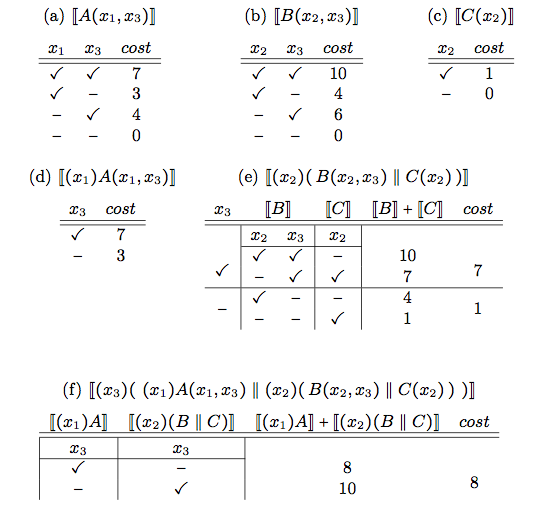
The resolution algorithm eliminates all the variables in the order they appear, from the inmost to the outmost one. It has the following steps:
- Elimination of x1: Table (d) is computed by forcing x1 to be inside A;
- Elimination of x2: Table (e) is computed by taking the best parking option for x2, i.e., the one that minimizes the total cost, for each possible value of x3;
- Elimination of x3: Table (f) is computed by taking the best parking option for x3.
Tracking back through the tables, we find the optimal variable assignment, namely: x1 and x3 inside A, with cost 3 and 4 respectively; x2 inside C, with cost 1.
Exploiting specific knowledge about the parking system, and the applicative scenario it is part of, we can apply some heuristics in order to reduce the complexity of the problem, possibly at the cost of having sub-optimal, but hopefully still acceptable, solutions. A few options are:
- Restrict the number of possible zones for each car. Keeping only some of the best parking options for each car makes the solution simpler. However, it may increase the total cost (and it may even make the solution impossible).
- Hierarchical organization of zones. Similar zones could be merged, leading to a smaller term. The hierarchy could depend on particular events such as soccer games, theater shows, etc.
- Bound size for tables. We could impose a maximum size for dynamic programming tables. Bigger tables could be replaced by some smaller ones, taking some averages (see [4]). The advantage is a lower storage cost and lower computational complexity of term evaluations.
Details and full proofs can be found in [7].
References
[1] Rossi, F., van Beek, P., Walsh, T.: Handbook of Constraint Programming (Foundations of Artificial Intelligence). Elsevier Science Inc. (2006)
[2] Bistarelli, S., Montanari, U., Rossi, F.: Semiring-based contstraint logic programming: syntax and semantics. ACM Trans. Program. Lang. Syst. 23(1), 1–29 (2001)
[3] Bueno, F., Cabeza, D., Carro, M., Hermenegildo, M.V., Lopez-Garcia, P., Puebla, G.: The ciao prolog system. Reference manual. Tech. Rep. CLIP3/97.1, School of Computer Science, Technical University of Madrid (UPM) (1997)
[4] Montanari U.: On the optimal approximation of discrete functions with low-dimensional tables. IFIP Congress (1971)
[5] Bures, T.,De Nicola, R., Gerostathopoulos, I., Hoch, N., Kit, M., Koch, N., Monreale, G.V., Montanari, U., Pugliese, R., Serbedzija, N., Wirsing, M., Zambonelli, F.: A Life Cycle for the Development of Autonomic Systems: The E-mobility Showcase. In: SASO, Awareness Workshop (2013)
[6] Monreale, G.V., Montanari, U., Hoch, N.: Soft constraint logic programming for electric vehicle travel optimization. In: 26th Workshop on Logic Programming (2012)
[7] Hoch, N., Monreale, V., Montanari, U., Sammartino, M.: Declarative vs procedural approach for scsp with an application to an e-mobility optimization problem (2014), Internal Report
On Detecting Significant Changes In Performance
Embedded in the very nature of adaptive systems is the ability to react to change - whenever there is a significant change in the parameters of the system or the surrounding environment, an adaptation is triggered. Common performance parameters, such as throughput or latency, are often among the triggers - however, deciding whether the observed change in performance is significant enough to warrant an adaptation is not an easy task.
To illustrate the difficulties, consider the ASCENS Cloud Case Study. A cloud application would often exhibit decreasing performance when faced with excessive workload - and an adaptive cloud application would react to this situation by allocating more processing capacity from the cloud. We pick one such application - an example XML processing server - and look at how such reactive adaptation works.
Our adaptation mechanism measures the request processing time and when the time exceeds a threshold, it launches a new XML processing server instance. From early testing, we know that the server should exhibit an average request processing time of around 100 ms. We use this average plus some slack to set the threshold - but when we deploy the application, the very first request processing time we collect is over 900 ms, well above even a very liberal threshold!
Obviously, the very first request cannot represent an excessive workload. We therefore turn to another obvious explanation, declaring the initial measurement distorted and therefore invalid. It is common to collect multiple measurements to filter out distortions, however, we cannot wait for too many measurements because that would increase the reaction time. We start with 30 measurements: 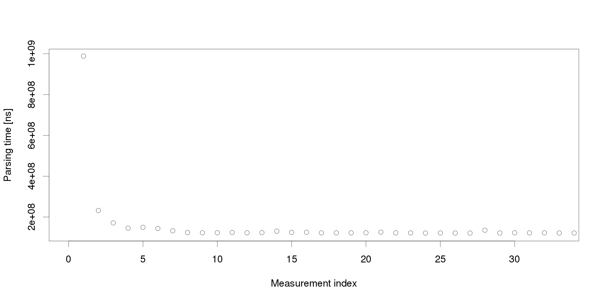
By looking at the graph, we can conclude that the measurements become stable after 5 observations. The remaining values differ very little and appear a suitable input for triggering adaptation. But collecting more measurements dispels this impression: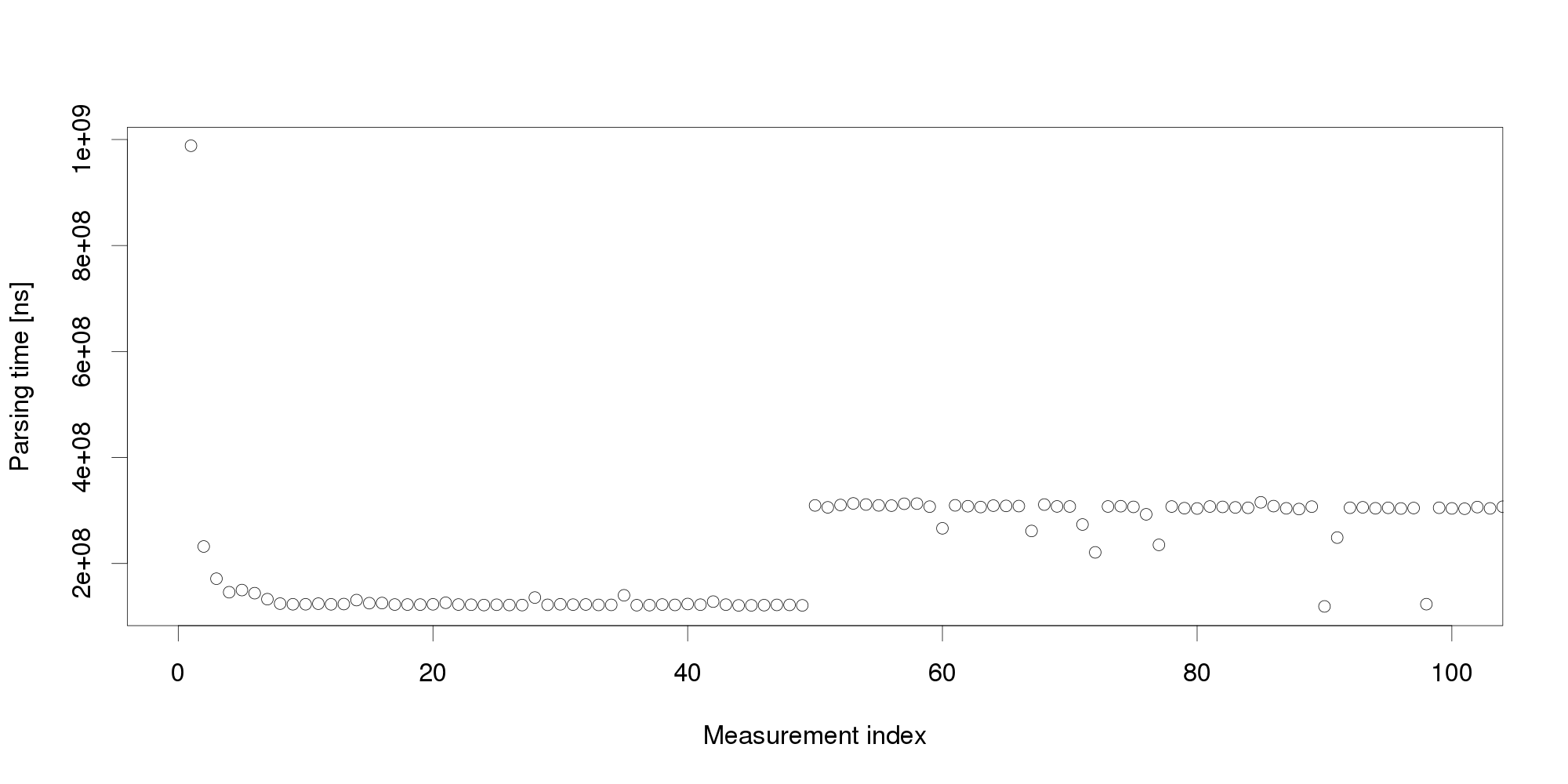 Pursuing the same line of thought, we can conclude that performance is not as stable as we originally thought, and add even more measurements:
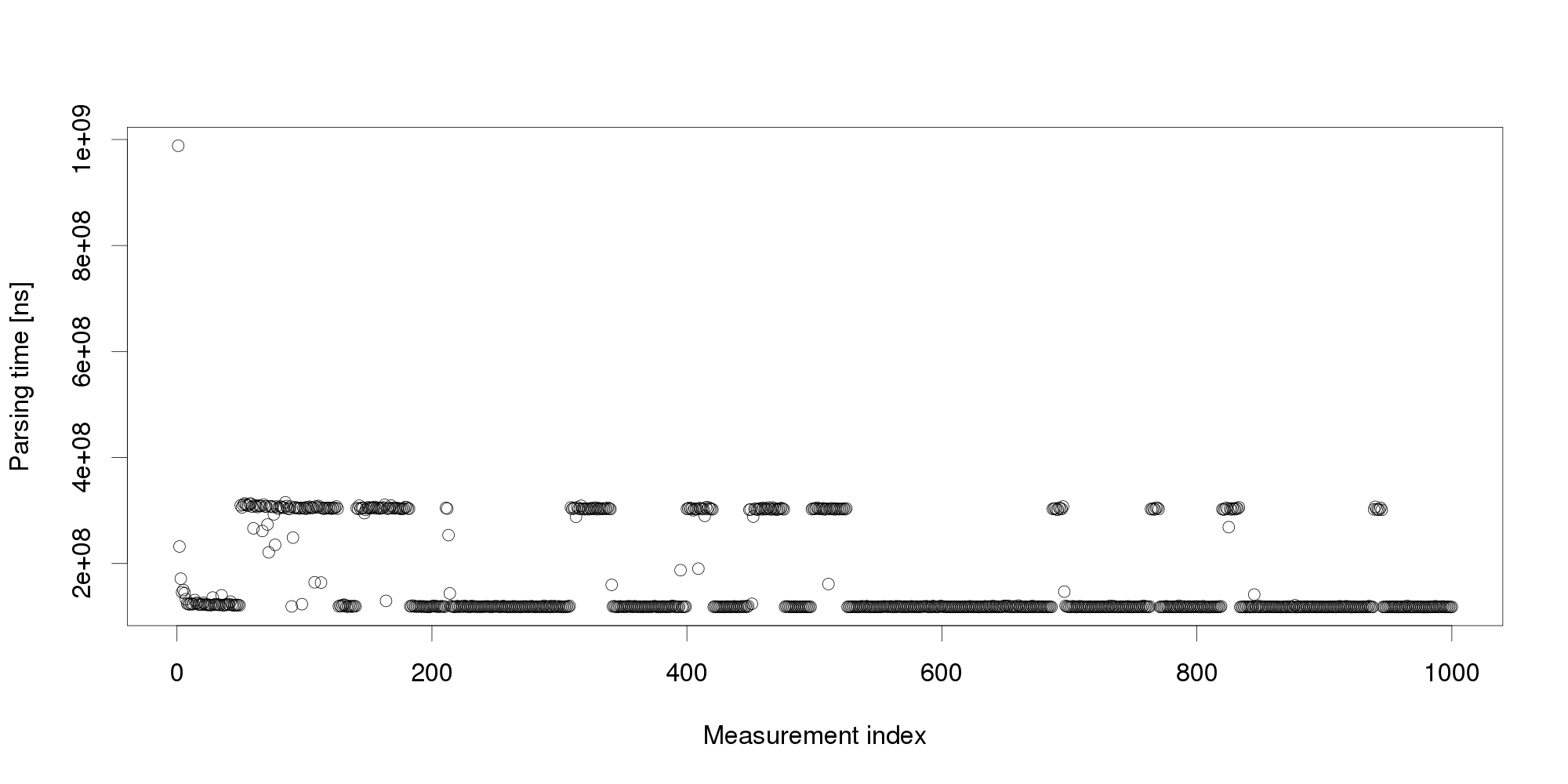 The graph shows that the change we have observed in the first 100 measurements is actually a common pattern. The XML processing server exhibits multiple performance modes that change at irregular intervals, and the processing time does not seem to stabilize in a reasonably short interval. More measurements after restart also show that the modes themselves are not necessarily stable:
Experience indicates this is not an unusual behavior. On the contrary, similar behavior can be observed with many software systems, and is often made even worse by additional measurement noise (here, we have measured the data under very stable controlled conditions to demonstrate our point). Obviously, mere threshold detection is not useful to identify changes.
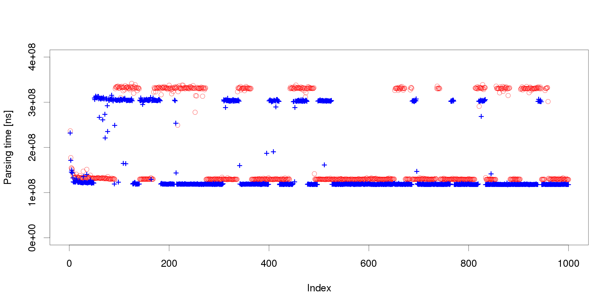
We address the issue with a novel non-parametric method that first learns what is an insignificant change to then detect the significant ones. The method bootstraps from historical data to compute the statistical properties of performance measurements under circumstances that do not require adaptation. Once this is done, the method requires only a few measurements to reliably detect whether they represent a significant performance change. To illustrate our results, we subject the XML processing server to a changing workload and use both our non-parametric method and Welch's t-test to detect changes in performance:
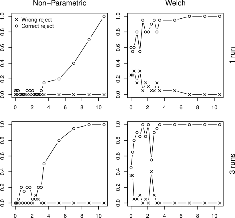
In all four graphs, the x axis shows the percentual change in workload size, the y axis gives the probability of detecting this change. The top row shows the detection after a single measurement, the bottom row does the same for three measurements. The "o" points mark correct change detections, the "x" points mark situations where the direction of the change was not detected correctly. We can see that in realistic conditions, the Welch's t-test would lead to frequent incorrect adaptation that our non-parametric method prevents. More details upon request (a publication is under review).
Vojtěch Horký
CUNI, Prague
Statistical Model-Checking
Computer systems play a central role in modern societies and their errors can have dramatic consequences. For example, such errors could jeopardize a banking system, possibly stalling the economy of a whole country or, more dramatically, endanger human life through the failure of some safety critical systems (railway signing, integrated avionics, air-traffic, medical life support machines, automotive electronics). It is therefore not surprising that proving the correctness of computer systems is a highly relevant problem. Unfortunately, the growing complexity in system design makes it almost impossible to ensure correctness simply by looking at the (possibly distributed) code. Automatic techniques are thus needed.
The most common method to ensure the correctness of a system is testing (see [3] for a survey). After the computer system is constructed, it is tested using a number of test cases with predicted outcomes. Testing techniques have shown effectiveness in bug hunting in many industrial applications. Unfortunately, testing is not a panacea. Indeed, since there is, in general, no way for a finite set of test cases to cover all possible scenarios, errors may remain undetected. There are also methods that can ensure the full correctness of a system. Those methods, also called formal methods, use mathematical techniques to check whether the system will behave correctly for all possible scenarios. Over the past, formal methods such as symbolic model checking [13] have been used to verify systems with more than 10^20 reachable states [4].
In an ideal world, it would thus be ``better'' to use formal methods rather than testing. Unfortunately, improvements in the development of formal methods do not seem to follow the increasing complexity in system design. Nowadays, most of formal methods suffer from the so-called state-space explosion problem, which makes them unusable for large industrial size applications. As testing does not suffer from the same problem, it remains the only scalable technique and is thus the one promoted by the industrials.
Statistical Model-Checking
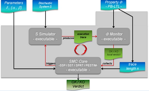
As we already said, the major drawback with testing is that, in general, it does not give any confidence on the correctness of the entire system. This lack of accuracy has motivated the development of new algorithms that combine testing techniques with algorithms coming from the statistical area. Those techniques, also called Statistical Model Checking techniques (SMC) [9, 15], can be seen as a trade-off between testing and formal verification. In fact, SMC is very similar to Monte Carlo used in industry, but it relies on a formal model of the system. The core idea of SMC is to monitor a number of simulations of a system whose behaviors depend on a stochastic semantic. Then, one uses the results of statistics (e.g. sequential hypothesis testing or Monte Carlo) together with the simulations to get an overall estimate of the probability that the system will behave in some manner. While the idea resembles the one of classical Monte Carlo simulation, it is based on a formal semantic of systems that allows us to reason on very complex behavioral properties of systems (hence the terminology). This includes classical reachability property such as ``can I reach such a state ?'', but also non trivial properties such as ``can I reach this state x times in less than y units of time ?''. Of course, in contrast with an exhaustive approach, such a simulation-based solution does not guarantee a result with 100% confidence. However, it is possible to bound the probability of making an error. Simulation-based methods are known to be far less memory and time intensive than exhaustive ones, and are sometimes the only option [10].
Statistical model checking is widely accepted in various research areas such as software engineering, in particular for industrial applications [1, 12, 7], or even for solving problems originating from systems biology [6, 11]. There are several reasons for this success. First, SMC is very simple to understand, implement, and use. Second, it does not require extra modeling or specification effort, but simply an operational model of the system that can be simulated and checked against state-based properties. Third, it allows us to verify properties [5, 1] that cannot be expressed in classical temporal logics. Finally, SMC allows to approximate undecidable problems. This latter observation is crucial. Indeed most of emerging problems such as energy consumption are undecidable [8, 2] and can hence only be estimated.
Saddek Bensalem
Verimag
[1] Ananda Basu, Saddek Bensalem, Marius Bozga, Benoit Caillaud, Benoit Delahaye, Axel Legay. Statistical Abstraction and Model-Checking of Large Heterogeneous Systems. In FMOODS/FORTE, 2010.
[2] P. Bouyer, U. Fahrenberg, K. G. Larsen, and N. Markey. Timed automata with observers under energy constraints. In HSCC, pages 61-70. ACM ACM, 2010.
[3] M. Broy, B. Jonsson, J.-P. Katoen, M. Leucker, and A. Pretschner, editors. Model-Based Testing of Reactive Systems, Advanced Lectures The volume is the outcome of a research seminar that was held in Schloss Dagstuhl in January 2004, volume 3472 of Lecture Notes in Computer Science. Springer, 2005.
[4] J. R. Burch, E. M. Clarke, K. L. McMillan, D. L. Dill, and L. J. Hwang. Symbolic model checking : 1020 states and beyond. Information and Computation, 98(2) :142-170, 1992.
[5] E. M. Clarke, A. Donzé, and A. Legay. Statistical model checking of mixed-analog circuits with an application to a third order delta-sigma modulator. In Proc. of 3rd Haifa Verification Conference (HVC), volume 5394 of LNCS, pages 149-163. Springer, 2008.
[6] E. M. Clarke, J. R. Faeder, C. J. Langmead, L. A. Harris, S. K. Jha, and A. Legay. Statistical model checking in biolab : Applications to the automated analysis of t-cell receptor signaling pathway. In CMSB, volume 5307 of LNCS, pages 231-250. Springer, 2008.
[7] E. M. Clarke and P. Zuliani. Statistical model checking for cyber-physical systems. In ATVA, volume 6996 of Lecture Notes in Computer Science, pages 1-12. Springer, 2011.
[8] U. Fahrenberg, L. Juhl, K. G. Larsen, and J. Srba. Energy games in multiweighted automata. In ICTAC, volume 6916 of Lecture Notes in Computer Science, pages 95-115. Springer, 2011.
[9] T. Hérault, R. Lassaigne, F. Magniette, and S. Peyronnet. Approximate probabilistic model checking. In Proc. of 5th Int. Conference on Verification, Model Checking, and Abstract Interpretation (VMCAI), volume 2937 of LNCS, pages 73-84. Springer, 2004.
[10] D. N. Jansen, J.-P. Katoen, M.Oldenkamp, M. Stoelinga, and I. S. Zapreev. How fast and fat is your probabilistic model checker? an experimental performance comparison. In HVC, volume 4899 of LNCS. Springer, 2007.
[11] S. K. Jha, E. M. Clarke, C. J. Langmead, A. Legay, A. Platzer, and P. Zuliani. A bayesian approach to model checking biological systems. In Proc. 7th Int. Computational Methods in Systems Biology, 7th Int. conference (CMSB), volume 5688 of LNCS, pages 218-234. Springer, 2009.
[12] J. Martins, A. Platzer, and J. Leite. Statistical model checking for distributed probabilistic-control hybrid automata with smart grid applications. In ICFEM, volume 6991 of Lecture Notes in Computer Science, pages 131-146. Springer, 2011.
[13] K. McMillan. Symbolic Model Checking. PhD thesis, Carnegie Mellon University,
1993.
[14] K. Sen, M. Viswanathan, and G. Agha. Statistical model checking of black-box probabilistic systems. In Proc. of 16th Int. Conference on Computer Aided Verication (CAV), LNCS 3114, pages 202-215. Springer, 2004.
[15] H. L. S. Younes. Verication and Planning for Stochastic Processes with Asynchronous Events. PhD thesis, Carnegie Mellon, 2005.
Design of ensembles with the most beautiful woman in the world
The vision of autonomic computing drives the development of cutting-edge software systems. We no longer want to create systems which are thoroughly administrated by hand. Once employed, the system should rather manage itself, keep itself alive and running. At the same time, ubiquitous computing and global interconnectedness introduce more and more nodes into our systems. They become highly distributed and need to operate in diverse and changing environments. Those systems challenge us to think of designs for autonomic systems with large numbers of possibly heterogeneous nodes. They may collaborate in many concurrently running ensembles, each fulfilling its global goal despite unforeseen and changing conditions. Their complex interaction behavior needs to be designed carefully while at the same time it must be equipped with flexible mechanisms to dynamically adapt to evolving environments. Well-known techniques, like component-based software engineering, are not sufficient for modeling such systems, but must be augmented with other features that allow to focus on the particular characteristic of ensembles.
In the HELENA approach [1], we propose a modeling technique for ensembles centered around the notion of roles. Ensembles are built on top of a component-based platform as goal-oriented communication groups of components. The functionality of each group is described in terms of roles which a component may dynamically adopt. Therefore, components can freely join and leave ensembles without breaking the overall functionality of the collaboration as long as another component takes over the abandoned role. Components also dynamically adapt to new situations by changing their roles or by concurrently playing several roles (maybe in different ensembles) at the same time. Hence, the conceptual key point of HELENA is that in a system several ensembles can be established in parallel with each participating component playing (possibly) different roles in different collaborations at the same time.
The following figure shows such an ensemble in graphical notation. The underlying component-based platform is a peer-to-peer network storing files where this ensemble is dynamically formed to retrieve a file from the network. To perform this task, we envision three roles: requester, router, and provider. The requester wants to download the file. First it needs to request the address of the peer storing the file from the network, while using the routers as forwarding peers of its request. Once the requester knows the address, it directly requests the file from the provider for download. Each role can be adopted by peer component instances, but offers different capabilities to take over responsibility for the transfer task, e.g. the request must be able to request the address of the provider from a router while the router must be able to receive the request.

An important characteristic of ensemble-based systems is that components are aware of their environment and adapt their behavior accordingly. HELENA is well suited to conceptualize an adequate architecture for such systems. We require each component to adopt a distinctive role which is responsible for monitoring the environment and making the component aware of significant changes. By changing old roles into new ones the component can adaptively react to these observations.
HELENA allows rigorous ensemble modeling based on a solid formal foundation. We define the architecture of communication groups as ensemble structures composed of roles and role connectors and enhance them to ensemble specifications by adding role behaviors. The formal semantics of an ensemble specification introduces an execution model which is given by an ensemble automaton. The states of an ensemble automaton describe which role instances currently exist and which component instances currently adopt which roles. An ensemble evolves over time by message exchange between collaborating roles or by performing management operations like creating new role instance.
For the execution of ensemble-based systems, we provide the Java framework jHELENA [2] which transfers the role concept to object-oriented programming and follows the rigorous semantics of HELENA models. HELENA models can be described either graphically in a UML-like notation or in a domain-specific language fully integrated into the Eclipse Development Environment [3]. A code generator transforms those models to jHELENA code for execution.
Annabelle Klarl
LMU
[1] Rolf Hennicker, Annabelle Klarl. Foundations of Ensemble Modeling - The Helena Approach. Specification, Algebra, and Software. 8373, 2014, Vol. Lecture Notes in Computer Science, pp. 359-381.
[2] Annabelle Klarl, Rolf Hennicker. Design and Implementation of Dynamically Evolving Ensembles with the Helena Framework. [ed.] IEEE. Proceedings of the 23rd Australasian Software Engineering Conference. 2014, pp. 15-24.
[3] Annabelle Klarl, Lucia Cichella, and Rolf Hennicker. From Helena Ensemble Specifications to Executable Code. International Symposium on Formal Aspects of Component Software. Lecture Notes of Computer Science. to appear 2014.
Feedback Loops in the Development of Autonomic Systems
The development of autonomous systems goes beyond addressing the classical phases of the software development life cycle like requirements elicitation, implementation and deployment. Engineering autonomic systems has also to tackle aspects such as self-* properties like self-awareness and self-adaptation. Such properties have to be considered from the beginning of the development process, i.e. during elicitation of the requirements. We need to capture how the system should be adapted and how the system or environment should be observed in order to make adaptation possible.
Models are usually built on top of the elicited requirements, mainly following an iterative process, in which also validation and verification in early phases of the development are highly recommended, in order to mitigate the impact of design errors. A relevant issue is then the use of modeling and implementation techniques for adaptive and awareness features. Our aim is to focus on these distinguishing characteristics of autonomic systems along the whole development cycle.
We propose a “double-wheel” life cycle for autonomic systems to sketch the main aspects of the engineering process. The “first wheel” represents the design or offline phases and the second one represents the run-time or online phases.
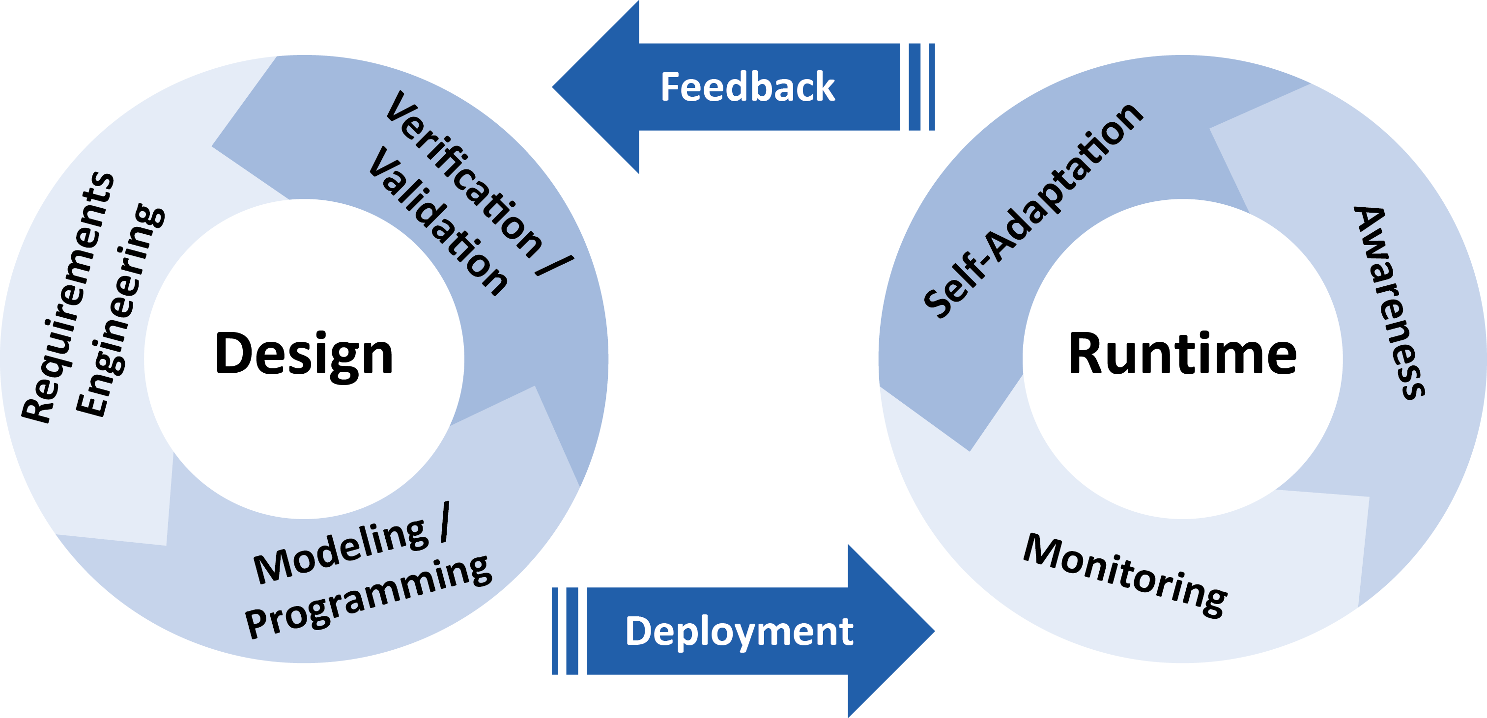
Both wheels are connected by the transitions deployment and feedback. The offline phases comprise requirements engineering, modeling and programming and verification and validation. We emphasize the relevance of mathematical approaches to validate and verify the properties of the autonomic system and enable the prediction of the behavior of such complex systems. This closes the cycle providing feedback for checking the requirements identified so far or improving the model or code. The online phases comprise monitoring, awareness and self-adaptation. They consist of observing the system and the environment, reasoning on such observations and using the results of the analysis for adapting the system and providing feedback for offline activities. Transitions between online and offline activities can be performed as often as needed throughout the system’s evolution, and data acquired during monitoring at runtime are fed back to the design cycle to provide information to be used for system redesign, verification and redeployment.
The process defined by this life cycle can be refined providing details on the involved stakeholders, the actions they perform as well as needed input and the output they produce. A process modeling languages can be used to specify the details. We can use therefore general workflow-oriented modeling languages such as UML activity diagrams2 or BPMN, or Domain Specific Languages (DSL) such as the OMG standard Software and Systems Process Engineering Metamodel (SPEM).
Within the ASCENS project several languages, methods and tools have been developed or previously existing ones have been extended to address engineering of ensembles. The development of a particular autonomic system will imply the selection of the most appropriate languages, methods and tools, i.e. an instantiation of the life cycle.
Can component policies be exploited by external reasoners?
In a scenario like the e-mobility one, e-vehicles should be equipped with reasoning units capable of dealing with unexpected events, like e.g., failure in booking a parking lot, traffic jams, or unavailability of booked parking lots. To react to these situations, appropriate actions should be determined and taken. We discuss the reasoning issue in the context of SCEL, a formal language developed to program autonomic computing systems in terms of the constituent components and their reciprocal interactions.
As shown in Figure 1, a SCEL autonomic component results from the interaction among knowledge and behavior components, according to specific policies. These provide a simple, yet expressive, linguistic tool for defining and enforcing rules to specify strategies, requirements, constraints, guidelines, etc. about the behaviour of systems and of their components.
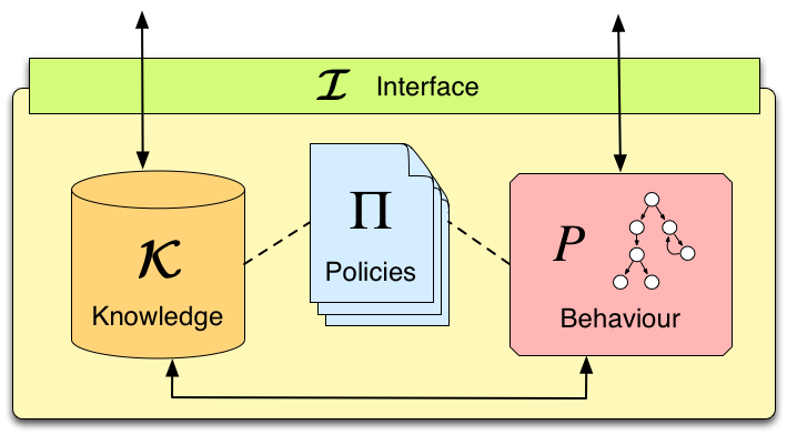
Figure 1: SCEL component
Policies may depend on the values of components' attributes (reflecting the status of components and their context) and can be dynamically modified for better reacting to system or environment changes. Moreover, as an effect of policy evaluation, specific actions, implementing adaptation strategies, can be produced at run-time and used to modify the behaviour of components.
Therefore, policies provide a simple form of self- and context-aware reasoning, supporting the achievement of self-* properties of the autonomic system. For example, when an e-vehicle is looking for available parking lots in nearby car parks, an internal policy could be used to ignore both parkings not equipped with charging station if the e-vehicle has a low battery level, and parkings with a cost per hour greater than a maximum cost established by the driver.
However, more sophisticated reasoning machineries can be necessary to deal with specific circumstances or when concerned with specific application domains. In these cases, separate reasoning units can be used by SCEL programs whenever decisions have to be taken.
Different reasoners, designed and optimised for specific purposes, can be exploited according to the components needs. Specifically, whenever SCEL systems have to take decisions, they have the possibility of invoking an external reasoner to receive informed suggestions about how to proceed. These answers would rely on the provided information about the relevant knowledge systems have access to and about their past behavior.
For example, in case of an unexpected event in the e-mobility scenario, a reasoner could be exploited by e-vehicles to dynamically re-plan their journey. Intuitively, the list of points-of-interest to be visited should be provided to the reasoner, which would shuffle it following some criteria, and would return the obtained list to the SCEL component that required it.
Figure 2 depicts such an enriched SCEL component, together with a generic external reasoner R. With respect to Figure 1, now local communications are filtered by a reasoner integrator RI (see post "Reasoning about reasoning agents").
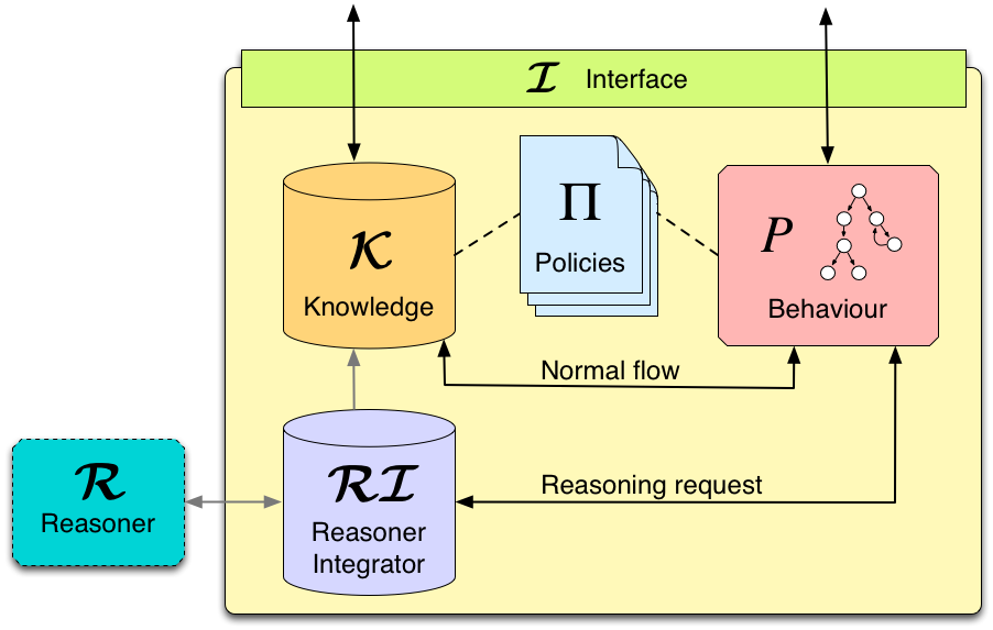
Figure 2: SCEL component with external reasoner
What we envisage is using policies not only for regulating components interaction, but also for managing the use of external reasoners. Policies could instruct the reasoners according to specific conditions on the internal status of the component and on external factors. For example, policies could urge the reasoner to return a solution as soon as possible, thus avoiding an exhaustive search. Moreover, policies could act as a filter for input data sent to the reasoner (e.g., sensible information about the driver could be removed from his profile before passing it to the reasoner), as well as for output data (e.g., actions returned by the reasoner could be blocked if they violate the e-vehicle polices). Anyway, as shown in Figure 3, how to reconcile policing and external reasoning is still an open issue.
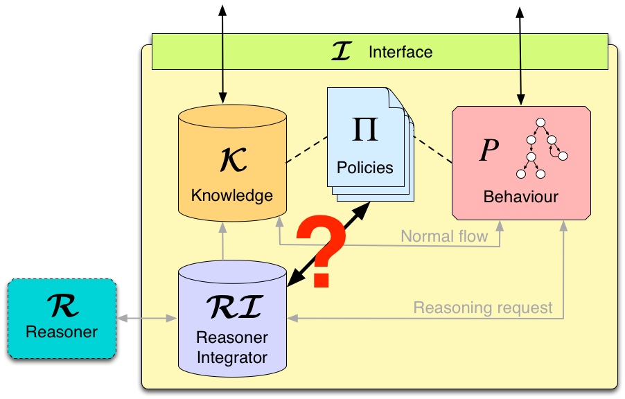
Figure 3: integration between policies and external reasoner
To tackle this issue, we should first be able to conceive under which conditions policies can help the reasoners, and to define appropriate interactions protocols between reasoners and policies handlers.
Rocco De Nicola and Francesco Tiezzi
IMT, Lucca
Beauty is in the eye of the beholder
The challenges of controlling the robot behavior in performing certain task can best be understood if seen from the robot perspective. The complexity does not necessarily come from the task itself, but rather from the interaction that goes on between the robot sensory system, environment and robot performance. The ASCENS project provides technology for autonomous behavior that can nicely be illustrated by a multi-robot control system. To show some of the project results we set a scenario where a human competes with an autonomous robot controlled by ASCENS software. The task is to find “building blocks” in a closed area and to construct a wall at a designated place. Of course a sensory system of the robots is less sophisticated than ours, thus we reduced the vision (perception) of the human competitor to the sensory system of the robot, giving the competitors equal chances. Both competitors have exactly the same information about environment. Who would perform better?

ASCENS philosophy: simplifying complexity
ASCENS explores perception, adaptation and self-organization offering high-level methods and practical tools for developing intelligent service-component ensembles that organize themselves and act autonomously. Under the motto simplifying complexity, the technological challenge is in controlling the dynamics of the emergent environments. Often we deal with massively parallel systems where harmonizing the communication and optimizing individual and collective goals is a major challenge. For example, how to build a powerful cloud platform that turns a huge number of simple devices into a super computer, or how to optimally organize mobility with electric vehicles taking into account battery restrictions, multiple itineraries and traffic conditions, or how to organize a rescue operation with self-aware and self-healing robot swarms.
The ASCENS approach to such complexity is to deal with issues at a local level, solving problems at a smaller scale and then harmonizing these solutions with more global ones. More concretely, a communication is organized in an implicit manner, who talks to whom is decided in run-time, depending on the current needs and situation. Thus, ASCENS approach decomposes complex systems into small service components (with clearly defined local goals) and then construct larger groups, called ensembles that fulfill collective goals. A criteria to construct an ensemble is a condition i.e. some “more global circumstance”, e.g. “ connect all robots that can carry 4kg and are in the radius of 100m – the goal is to jointly transport 15kg heavy object”. Having the knowledge as a major criterion for communication leads to self-awareness (where awareness can be defined as the knowledge of own functional and operational requirements and states). Making ASCENS components and ensembles aware of their own capabilities and goals ensures adaptive and autonomous behavior at runtime.
ASCENS approach: both pragmatic and formal
Pragmatic orientation means building autonomous systems that do practical things, like autonomous robot swarms performing rescue operation, autonomous cloud computing platforms transforming numerous small computers into a super computing environment or autonomous e-mobility support that ensures energy-aware transportation services. In reality, autonomous behavior means functioning without human intervention, seamlessly using own rules and criteria. At runtime, the more autonomy the system exhibits the less obvious it appears to outside observers. Thus to be sure about correct functioning of such systems it is necessary to develop formal methods and tools that can ensure not only that an autonomous system really does what it is supposed to do, but also that important conditions of the whole controlled environment are never violated. ASCENS offers a range of formal means that ensure modeling, formal reasoning, validation and verification of complex controlled systems, both in its design and at runtime.
ASCENS at ICT 2013 – science and joy
The picture below shows our stand at ICT 2013. Our team put enormous effort to make the robot versus human competition system, fine-tuned just for ICT 2013 purposes. Not only that both robots - ASCENS and human controlled - worked perfectly, the response of the audience has been rewarding. We are having many visitors, hundreds of questions and a lot of fun!

Nikola Serbedzija
Fraunhofer, Fokus
Reasoning about reasoning agents
Ensembles are systems consisting of a massive number of components that have the ability to dynamically adapt to environments that may change heavily during runtime. They pose a number of challenges. On the one hand, parallel activities of many heterogeneous components calls for knowledge sharing and coordination. On the other hand, dealing with changing environments and nondeterministic behaviors requires enabling ensemble components to reason about actions to take and their impact.
Auto-scooter, or “how to avoid bumpings”
Consider a grid world with an arbitrary number of agents moving in it. At every time step, agents can move up, down, left, right or decide to stand still. We concentrate on a single, partially informed agent that wonders in the area paying attention to minimizing its collisions with other, randomly moving, agents. Our agent perceives local information about the environment, but up to a limited perception range and has to exploit the available information to minimize collision risk.
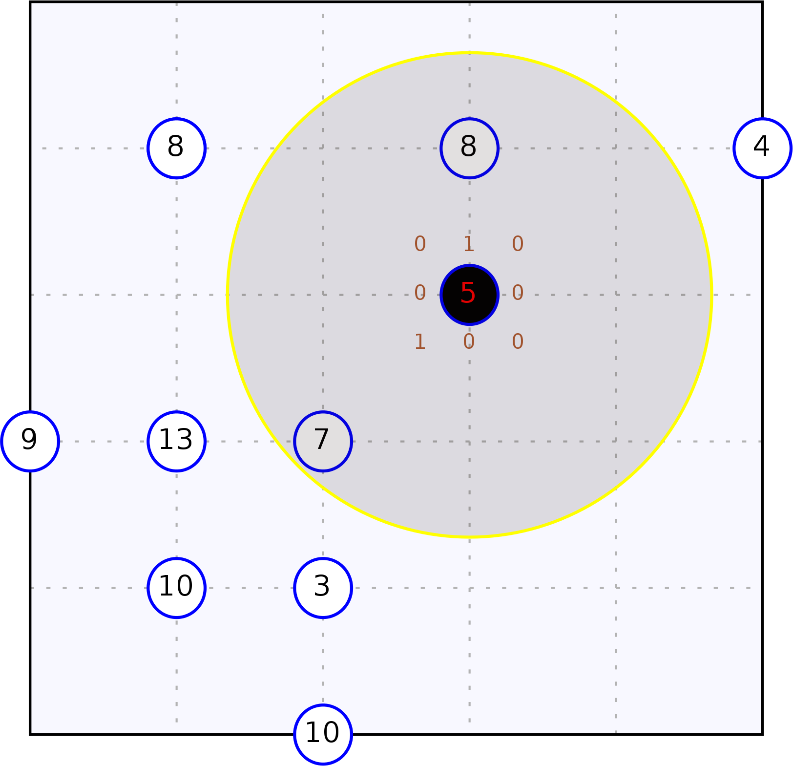
The figure depicts the scenario from a bird-eye perspective. The informed agent is the black circle surrounded by a wider semi-transparent circle representing its perception range. Blue circles represent randomly moving agents. Robots are labelled with their current number of collisions.
Modelling activities
In order to make an agent avoid others, as desired in the outlined scenario, it obviously has to move actively. The SCEL language [1] has been proposed to specify component behavior and to deal with the challenges that arise from the coordination of a massive number of components running in parallel. SCEL supports attribute-based communication and the management and sharing of information through tuple spaces that can for example serve as knowledge repositories. For the particular scenario, a SCEL implementation in the Maude language, MISSCEL, has been used to specify the informed agent's controller program. Maude provides a logical specification framework that allows to formally define the computational and deductional semantics of a language [2]; it also provides support for statistical model checking by the PVeStA tool [3].
Smart activities
In order to allow components to reason about actions to take, and thus to enable them to act autonomously and perform runtime adaptation, SCEL programs specifying components behavior can be connected to a reasoner. In the considered case study, the used reasoner is PiRLo [5], but the approach is viable for any reasoning system that can be triggered by a SCEL program via the tuple space. The fact that also PiRLo is written in the Maude language facilitates integration and allows for seamless usage with PVeStA. By using the formal approaches developed in the course of the ASCENS project, i.e., MISSCEL for modeling agents behaviors behavior and PiRLo for providing reasoning capabilities, it is possible to formally prove the quality of provided solutions. The PVeStA tool is used to generate measures that permit empirically comparing different solutions.
A headache: Formalisms integration
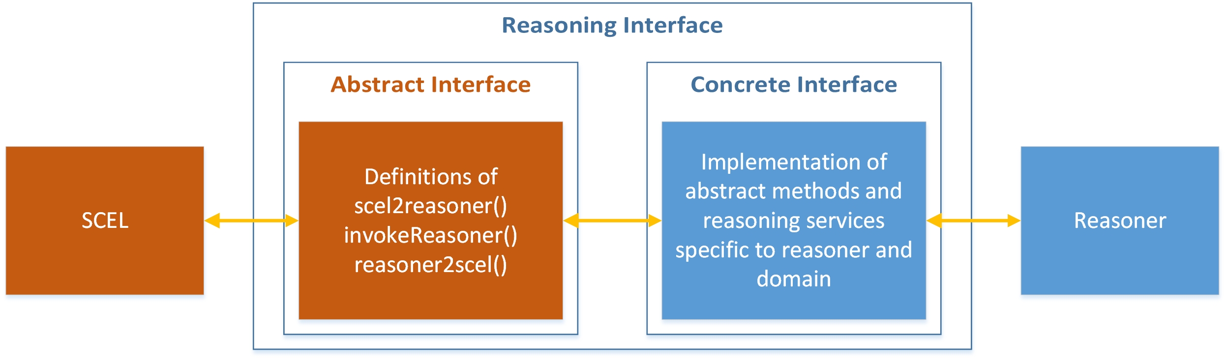
A common repository is used to integrate PiRLo with MISSCEL. There agents store their current perception and requests of specific services for the reasoner. When a SCEL program finds “reasoning tuples”, it invokes the reasoner via an abstract SCEL-reasoner interface. The wanted answer is obtained after three steps:
- Syntax and parameters of the reasoning request are translated from SCEL's representation to the reasoner's one.
- Reasoning is performed according to the requested reasoning service.
- Results provided by the reasoner are added to the tuple space of the requesting SCEL program.
Appropriate interfaces between the reasoner and SCEL guarantee a smooth interactions and hide implementation details of the adapter (consisting of both the abstract and the concrete interface). The figure below graphically outlines this approach.
At work!
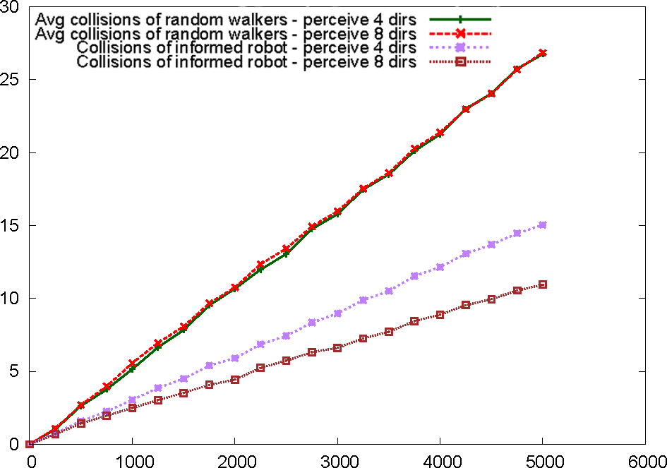
By providing a formal specification of the scenario in MISSCEL and PiRLo, it is possible to use a formal statistical model checking approach to empirically measure the quality of the proposed solutions. We implemented a SCEL program gathering information about the environment at every time step and triggering a reasoning service that provides the movement direction with the lowest probability of colliding with other agents. Upon receival of the wanted information, the informed agent moves as indicated by the reasoner. To evaluate the quality of the SCEL program, we measured the number of collisions detected in 5000 steps of simulation and compared the performance of our informed agent with that of an agent moving randomly. The figure below shows the results achieved by using the PVeStA statistical model checker. We considered two scenarios concerning an arena with 5*5 cells containing 10 normal robots and an informed one, all probabilistically distributed in the arena. In the first scenario the informed robot perceives only the four surrounding (4 dirs) positions while in the second it perceives also the positions along the diagonals (8 dirs). As one can would naturally expect, the integration of a reasoner improves the solution quality (i.e. reduces the numbers of collisions); through the presented approach of formal specification and statistical model checking, this intuitive result can also be proven empirically. The following image shows the results of the performed statistical analysis, while the video shows an exemplary simulation run.
The moral of the story
This blog presented an approach for rapid prototyping of service component ensembles that act autonomously in highly dynamic environments. To achieve this, component behavior has been specified in the MISSCEL implementation of the SCEL language and the PiRLo reasoner has been successfully integrated to MISSCEL via a well-defined interface to improve solution quality while maintaining separation of concerns. The presented approach for integration of reasoning via services is not limited to the particular implementations of SCEL or any reasoning component; it can be straightforwardly used for other implementations as well. As both the implementations of MISSCEL and PiRLo are realized in the Maude language, statistical model checking of provided solutions with the PVeStA model checker is straightforward. We provided evidence of the usefulness of the approach by comparing a solution exploiting the reasoner and one where agents only performs random movements.
A paper [5] detailing the results presented in this blog is under preparation.
In the future, we will look into hordes of reasoning agents (ensembles, yay!), e.g. by letting them explicitly talk to each other about their 'mental efforts'. Also, we could render the agents even smarter (yes, it is possible!), for example by providing them particular ontologies about the world they act in - already looking forward to some autoscooter-ontology.
If you'd like to know where we know all this from...
[1] De Nicola, R., Loreti, M., Pugliese, R., Tiezzi, F.: SCEL: a language for autonomic
computing. Tech. rep. (January 2013)
[2] Clavel, M., Duran, F., Eker, S., Lincoln, P., Marti-Oliet, N., Meseguer, J., Talcott,
C.L.: All About Maude, LNCS, vol. 4350. Springer (2007)
[3] AlTurki, M., Meseguer, J.: PVeStA: A parallel statistical model checking and
quantitative analysis tool. In: Corradini, A., Klin, B., Cîrstea, C. (eds.) CALCO
2011. LNCS, vol. 6859, pp. 386-392. Springer (2011)
[4] Belzner, L.: Action Programming in Rewriting Logic, to appear
[5] Rewriting Logic and Autonomic Computing: Modelling and Reasoning about Service Component Ensembles, by L. Belzner, R. De Nicola, A. Vandin and M. Wirsing, under preparation