What can Formal Methods do?
In a post of F. Tiezzi to this blog, titled “Robot Swarms – What can Formal Methods do?" it has been shown that Formal Methods (FMs) can support the development of models of real (robotics) systems and that such models can be used for system simulation. It has also been (correctly!) argued that such simulation offers many advantages, especially when compared with experimentation on the real system, e.g. in terms of cost. A possible objection to Francesco’s point could be: couldn’t simulation be performed as well using models built without the use of formal modelling languages and supporting theories? In the end, this is what computer professionals have been doing for decades . . . In other words, Francesco deliberately avoided addressing the issue ‘per se’ of the role of FMs in Computer System Engineering (SE), including the engineering of complex systems of autonomic service component ensembles.
In this post I’ll try instead to focus on this very issue. The reason why I decided to do so is that my personal experience induces me to think that the role of FMs in SE is still not fully appreciated in the Computer Science (CS) community, not even in the more intellectually sophisticated part thereof, namely in the CS research community. So, I think that a few considerations on this subject might help the reader understanding also why a great deal of ASCENS effort is devoted to the development of formal modelling and analysis languages and techniques. Of course, I have to apologize with all colleagues in the area of FMs, and in particular with ASCENS friends, for inaccuracies, and incomplete or obvious statements which unavoidably will pop up in my post; on the other hand, being this the public ASCENS blog I ask knowledgeable people to tolerate my superficiality, if this can help a broader community getting a chance to appreciate the role of, and the motivations for FMs. And, ultimately, also their role in ASCENS.
My first and, I’d say major, observation is that this lack of appreciation for FMs seems to be a peculiarity of people’s attitude towards SE, not at all experienced when considering other branches of engineering. Let me start by quoting C. Jones [Jon00]: “All engineering disciplines make progress by employing mathematically based notations and methods.” Notice that the above consideration applies to all engineering disciplines, and it explicitly refers to notations and methods that are mathematically based. Is this true?
Let us consider civil engineering. In this case, graphical notations, among others, are widely used, and this goes on now for quite a long time (see the figure below [MaJ06]):
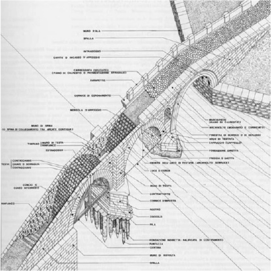
Although the result of using such graphical notations can be quite evocative, and may bear some artistic value, it is worth noting that technical drawing is regulated by rather strict rules. Such regulations are often internationally standardized and amazingly detailed (I still remember that when I was an undergraduate student, we were thought, at a technical drawing course, that when we draw a certain kind of arrows, the width of the tip should be in a fixed relationship with its length---1/3, to be precise, if I remember well!---in order for the arrow to be a “correct” one). Furthermore, we were thought specific techniques for constructing, or better, (almost) mechanically generating, “sections” of objects. Well … essentially, we were thought rigorous, sometimes formal, rules for drawing models of the artefacts we were designing, be them bridges or taps. To a certain extent, these rules were a rigorous definition of the syntax to be used for creating our models. On the other hand, the sectioning/projecting techniques were based on formal rules of mechanical manipulation of the drawings, . . . a, maybe rudimentary, form of model analysis based on formal semantics. Furthermore, in most cases, such drawings were decorated with numbers which could be used in mathematical formulas in close relation with (parts of) the drawings, or derivable from them (think, for instance, at the calculation of the max load which can safely cross a bridge, starting from the sizes, materials, and geometric relationships of the relevant components of the bridge, using the laws of statics).
Another example of the close relationship between design notations and maths in the tradition of engineering is the design of electrical circuits. Below there is a typical (although dated!) example thereof, related to a commercial device (copyright PHILIPS):
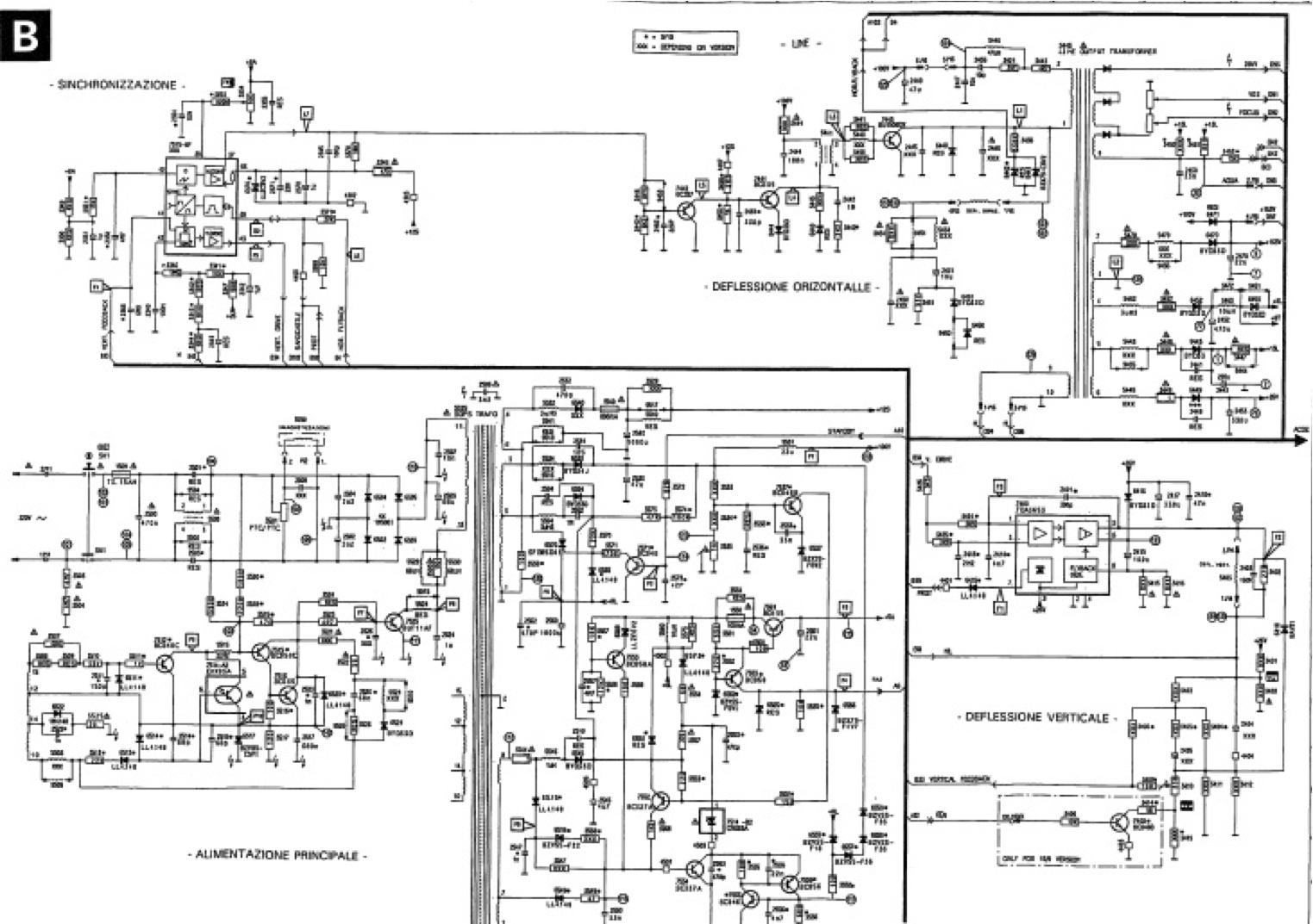
You can see several instances of different kinds of components, connected in certain ways and with annotations, typically referring to (physical) quantities related to electricity. I want to elaborate a little bit more on electrical circuits and maths. To that purpose, let's use a simpler schema, which we all have probably got acquainted with at high school, the so-called RLC circuit.
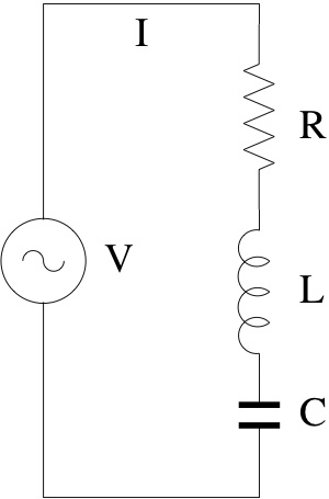 We immediately note that there are some basic components (for resistors, inductances, capacitors, etc.), possibly with some quantities associated with them, and standardized systematic ways of composing them (e.g. in series, in parallel, in series-parallel, etc.). Again, although the above graphic descriptions are quite evocative of the physical objects they represent, we can use them for reasoning about our designs in rather abstract and often mechanical ways, with the help of some math, and without necessarily having to experiment repeatedly with physical realizations of our circuits. For instance, as you will remember, by using Kirchhoff laws, we can predict that the resistance offered by the circuit below at its terminals is R=R1*R2/(R1+R2).
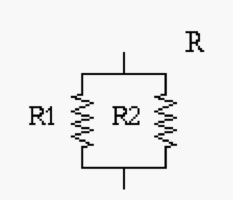
This formal, mathematical, relationship between R, R1, R2 and the associated composition diagram allows us to replace, in any circuit, e.g. the RLC one above, a resistor of a given resistance R, say 8 Ohm, with the parallel composition of two resistors R1, R2, of, say, 16 Ohm. Notice that we can make those manipulations directly on the graphical schema, even mechanically, provided the above equality is not violated. On the other hand, the above equality comes from specific laws of physics, which are, in turn, expressed as math formulas. Although we have been using a graphical notation for circuits, I’m sure you will understand that we could describe our systems using textual notations instead, based on operators, like, say, PARALLEL(x1,s2) or SERIES (x1,x2), etc.
A closer look at the RLC circuit, and some basic knowledge of physics, allow us to express the relationships between the components of the circuit and the physical quantities of interest, e.g. the current i and voltage v at the power unit terminals (PU), at any point in time, as follows:
![]()
The solution of the above equation gives a current that changes over time with a sine like shape
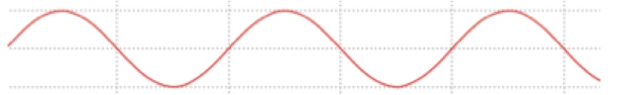
The frequency w of the sine is that specific of the PU. It is useful to study how the amplitude of the above signal, i.e. the (absolute) value of the peaks, changes with w. It can be shown that (for appropriate values of R, L, and C) as w increases from 0 the amplitude increases as well, reaches a max and then decreases again, as follows:
 The frequency corresponding the amplitude peak is the so-called resonance frequency (RF). Why is the RF so important? And, most of all, why am I bothering you with all these details? Both questions are easy to answer! The identification and study of RFs are of paramount importance in the design of systems that might be subject to oscillations (these include RLC circuits, but also bridges, ships, or aircrafts, for example); to be brief: devices and systems can be seriously damaged by too high oscillation amplitudes (bridges can crash, ships can sink or brake down...). For what concerns the second question, I used the above example for showing you that, starting from a diagram, sometimes called a blueprint, i.e. a formal syntactical description of a model of a system, and doing some manipulations of its semantics with the help of mathematics, we can characterize some peculiar features of the system we are designing. The document where the relevant peculiar features of a system are specified is the so-called technical specification, also called, in our, CS, domain, requirements specifications document. Needless to say, it is convenient that also such a document be as much rigorous as possible, even better, if it also includes some logic/mathematical formulas, as is the case for RLC systems (because this helps in having unambiguous specifications of the requirements). The process of relating a design model with the requirements specification can be seen as a process of abstraction and, of course, appropriate notions should be available also for checking that a design model satisfies a given requirement. But do we have to do all this by paper and pencil or only experimental testing? Fortunately not: we can play with software tools (see, e.g. http://ngsir.netfirms.com/englishhtm/RLC.htm), even forgetting, while designing and only to a certain extent, that behind all these activities there is a huge and solid body of mathematics supporting them, including Set Theory, Continuous Mathematics, Metric Spaces, Differential Calculus and Function Analysis, Linear Algebra, Differential Equations, just to mention a few ...
Summarizing: Civil, Naval, Nuclear, Electrical, Electronic (. . .) Engineers use notations for technical specifications (requirements specifications) as well as design specifications/models that
- are strongly based on mathematics (and physics),
- are compositional (at least in a broad sense),
- are characterized by great and flexible descriptive power,
- allow for the formal manipulation of their objects
- are heavily supported by computer (software) tools (e.g. for model analysis, including relating models to technical specs)
Society expects engineers to be aware of the underlying theories although not necessarily to be able to completely master them. I repeat it: a good, or even average, civil, electrical, etc. engineer, is socially not allowed to claim he can do without formal methods. And now: what about engineers designing complex, critical, computer/software systems? Although in the past there have been people, including respectable scientists, who have been arguing that SE is mainly a matter of art, or, at most of kraft-work, there is now some consensus, at least in the SE community itself, that it is a matter of engineering and so, as in any other branch of engineering, besides ingenuity and inspiration, there is need of systematic application of sound methodologies and techniques, with a solid mathematical basis.
But then, the question is what is the logics/mathematics basis of SE: what kind of mathematical objects, theories and techniques can best support the design activities typical of SE. I’ll touch upon these issues soon, in my next post.
[Jon00] C. Jones. Thinking Tools for the Future of Computing Science. In R. Wilhelm, editor. Informatics 10 Years Back 10 Years Ahead, volume 2000 of Lectures Notes in Computer Science. Springer-Verlag, 2000 112-130
[MaJ06] M. Mazzoleni, L. Jurina ``PONTI IN MURATURA: DIFETTI E PATOLOGIE'', CIAS 2006, Bolzano